OEM Hub
This is kept here for historic information
As new firmware has been applied to all V1 Hubs, unless you have not had it connected to the internet since 2021 then your hub will have been upgraded and unable to use this.
Hub Variants
Hub V1 No FCC Link Hub V2 FCC https://fccid.io/XO9-IHB002
The hub is where all my effort has focused, as most likely you already own a the Hub so why not use it rather than my other attempt at building a whole hub replacement.
Credentials
The Hub boot process:
- Powers on and ears alternate flash red showing it is booting.
- Syncs NTP time to
pool.ntp.org - Does a x-www-form-urlencoded POST to
https://hub.api.surehub.io/api/credentialswith Serial Number and Mac Address to retrieve the credentials.
With the semi recent build of the Hub Firmware to 2.201 the hub now checks the certificate it is connecting to is legimate, which is annoying since just posioning DNS was sufficient, but now you must also downgrade firmware to 2.43 which the old firmware build process is included. So after the initial build has happened downloading the start information the script then downloads all firmware and builds the firmware.
Example CURL to retrieve credentials
fw=2.43
serialnumber=H0xx-0xxxxxx
macaddress=0000xxxxxxxxxxxx
curl -v -k -d "serial_number=$serialnumber&mac_address=$macaddress&product_id=1&firmware_version=$fw" -H "curl/7.22.0 (x86_64-pc-linux-gnu) libcurl/7.22.0 OpenSSL/1.0.1 zlib/1.2.3.4 libidn/1.23 librtmp/2.3" -H "Content-Type: application/x-www-form-urlencoded" -X POST -o $serialnumber-$macaddress-$fw.bin https://hub.api.surehub.io/api/credentials
The response comes back as text/html; charset=utf-8 with the payload:
If the HTTP Header X-Upgrade: 1 is included in the HTTP response then it forces a Firmware Update.
v02:ssssss:uuuuuuuu-uuuu-uuuu-uuuu-uuuuuuuuuuuu:::1:v2/production/uuuuuuuu-uuuu-uuuu-uuuu-uuuuuuuuuuuu:a5kzy4c0c0226-ats.iot.us-east-1.amazonaws.com:MIIKL...Client Cert...AgIIAA==
The credentials response contains a colon : delimited file which is used to configure the hub each time it boots, it also means that to run completely offline you need a backup of the credentials file.
The decoded credentials are also printed to the console output when the hub boots.
-------- Credentials Decoded --------
	Host:		a5kzy4c0c0226-ats.iot.us-east-1.amazonaws.com
	Client ID:	uuuuuuuu-uuuu-uuuu-uuuu-uuuuuuuuuuuu
	Base Topic:	v2/production/uuuuuuuu-uuuu-uuuu-uuuu-uuuuuuuuuuuu
	Version:	v02
	ID:		ssssssuuuuuuuu-uuuu-uuuu-uuuu-uuuuuuuuuuuu
	Username:
	Password:
	Network Type:	1
	Certificate:	MIIKL...Client Cert...AgIIAA==
 	Length:		2611
	Cert Hash:	0x..
	Key Hash:	0x..
-------- End Credentials --------
The fields
| Field | Example Value | Description |
|---|---|---|
| 0 | v02 | Version, which is always 'v02' |
| 1 | ssssss | ID which is serial number after the - with no leading zeros IE H010-0123456 the serial would be 123456 |
| 2 | uuuuuuuu-uuuu-uuuu-uuuu-uuuuuuuuuuuu | Client ID which is just an AWS issued UUID for the MQTT Client ID |
| 3 | MQTT Username, which is blank but can be set if your local MQTT broker requires authentication | |
| 4 | MQTT Password, which is also blank but can be set as required | |
| 5 | 1 | Network Type, always set to 1 |
| 6 | v2/production/uuuuuuuu-uuuu-uuuu-uuuu-uuuuuuuuuuuu | Base Topic, this is updated to pethub/hub/H0xx-0xxxxxx for pethublocal |
| 7 | xx | Certificate a base64 encoded PKCS12 AWS issued Client Certificate with a password that is hard-coded into the hub flash |
Once the credentials file has been decoded then the ears change from alternating red, to alternating green.
MQTT Messages
- The Base Topic in the
credentialsresponse in field #6 from the cloud points to AWS IoT Base topic, they use a AWS generatedUUIDfor both the Client ID and part of the Base Topicv2/production/uuuuuuuu-uuuu-uuuu-uuuu-uuuuuuuuuuuu - All messages are sent with MQTT QoS
1, rather than0 - Whenever a hub sends a message the cloud replays exactly the same message back to the hub. I have no idea why, but it does. The Hub doesn't stop working if it doesn't retrieve a replay of the message back so I don't do that in PetHubLocal.
Messages from the hub:
- Base Topic +
/messages- Hub messages - Base Topic +
/messages/yyyyyyyyyyyyyyyy- Device messages whereyyyyyyyyyyyyyyyyis the MAC Address of the device.
Publish messages mosquitto_pub:
mosquitto_pub -q 1 -t 'pethub/hub/H0xx-0xxxxxx/messages' -m '62852aad 1000 ...'mosquitto_pub -q 1 -t 'pethub/hub/H0xx-0xxxxxx/messages/yyyyyyyyyyyyyyyy' -m '62852aad 1000 ...'
Last Will
The Last Will Message is a non-standard messages. When the Hub Connects it publishes the last will to the *base topic* + /messages topic with the message:
Hub has gone offline (having been online since dd hh mm ss)
Where dd is the day of the month. and hours, mins and seconds in UTC time, not zero padded. This way SurePet / AWS knows when the hub goes offline if you unplug the hub or the network gets interrupted the last will message will be sent.
Common message characteristics
- The messages are space delimited with a fairly standard message format with a few quirks which is to be expected.
- Time - All time is in
UTCwith the exception of the Pet Doors which set the curfew in Local Time as that is what is displayed on the LCD screen. - The command vs status message messages are determined by the counter being either
0xx0for a status message which is a single byte counter forxxor1000for the command message to send an action to the hub. - Message Counters - Are either single or double bytes.
- Two classes of devices, Hubs + Pet Doors and everything else.
- The Hub and Pet Door send registers so have memory / register offset plus the register value that is changing or being set. These are sent as
132messages. - All other devices, Cat Flap, Feeder and Posedion all send
126and127message type payloads where126is a status multi-message with message length and message type and there can be multiple messages sent in a single payload, and127is a command message with just message type, and there is no length as only one message can be sent in a command message.
- The Hub and Pet Door send registers so have memory / register offset plus the register value that is changing or being set. These are sent as
- You will also notice the Last Will message doesn't have a timestamp or counter. Since, you know, why have a standard message format when you don't need to.
| Offset | Example | Description |
|---|---|---|
| 1 | 626e685b |
Event Timestamp in UTC hex format |
| 2 | 0010 or 1000 |
Status or Command message where status is 0xx0 and command is 1000 for messages from devices or the hub, or making changes |
| 3 | 2 or 3 or 8 or 10 or 126 or 127 or 132 |
The message type depending on which device is generating it |
| 4+ | ... | Depends on the payload |
Hub message characteristics
Specifics of the Hub message ontop of Common message characteristics Hub Message Type:
2Command to set multiple bytes to the Hub3Command to query registers10Status to report Hub Uptime hourly132Status register update
Hub Example messages
| Type | Example | Description |
|---|---|---|
| CMD - Flash Hub LEDs | 6283d4fb 1000 2 18 1 80 |
Send command to set register 18 one 1 byte to 80, which causes the Ears to flash green three times, then go to off |
| CMD - Query Registers | 6283d4fb 1000 3 0 205 |
Send command to query the Hub Registers from offset 0 to offset 205 |
| Status - Hub Uptime | 6283d4fb 0020 10 00003480 01 12 34 56 6283d4fb 1 |
Counter 0020, Uptime Type 10, Decimal minutes up 00003480, UTC time 01 12 34 56 - dd hh mm ss, Reconnect counter 1 increments each time hub reconnects to MQTT |
| Status - Hub Online | 6283d4fb 0000 Hub online at 17 17 1 47 |
First boot message when the hub boots, the counter is 0000 and the time stamp is mm hh mm ss in string format |
| Status - Hub Register Update | 6283d4fb 0010 132 0 0 8 01 cd 00 02 00 2b 00 03 |
First register message, 0010 Status counter, 132 register, counter 0, offset 0 and length of 8 with the registers 0 through to 7 being sent |
Hub 132 Register messages
| Offset | Example | Description |
|---|---|---|
| 3 | 132 |
132 register status update |
| 4 | 1 |
Single byte decimal counter that goes from 0 to 254 before repeating, not zero padded |
| 5 | 0 to 205 |
Starting decimal register offset, this is the starting offset of the register not zero padded |
| 6 | 1 to 8 |
Payload length, from the above register, the proceeding bytes are the reigster(s) changing not zero padded, maximum length of 8 for each message |
| 7+ | xx |
Payload data in Hex byte, this is zero padded for the hex value |
With the above understanding of the different message formats, the registers sent in the 132 messages are documented below from my understanding.
| Register | Description |
|---|---|
| 3-6 | Firmware Version, High value 3&4, Low value 5&6 so 2.43 = 02 00 2B 00 |
| 7 | Hardware Version |
| 15 | Adoption Mode to adopt new devices - Disabled (0), Enabled (2), Adopt using bottom Button (0x82) |
| 18 | Flash LEDs - Off (0), Bright (1), Dimmed (4), Flash then Off (0x80), Flash then Bright (0x81), Flash then Dimmed (0x84) |
| 23 | MIWI Channel Noise Floor |
| 24 | RF Channel Register, Channel 1 - 15 (0f), Channel 2 - 20 (14), Channel 2 - 26 (1a) should be always 0x0f |
| 31-34 | Device uptime |
| 44 | Number of registered devices |
| 45-52 | Registered Device 0 Mac Address - 8 Bytes |
| 53-60 | Registered Device 0 State - 8 Bytes |
| 61-68 | Registered Device 1 Mac |
| 69-76 | Registered Device 1 State |
| .. | Device 2 - 8 |
| 189-196 | Registered Device 9 Mac |
| 197-204 | Registered Device 9 State |
Device Status
The 8 Bytes for each device after the Mac address can be further broken down as:
| Byte | Description |
|---|---|
| 0 | Status, First bit is Valid True/False, Second bit Online / Offline, Bit 3+ Product ID ie 3 for Pet Door |
| 1-3 | RSSI Value I guess, still haven't figured this out |
| 4-7 | Last heard, signed integer which is displayed on the serial console as well. Some timestamp |
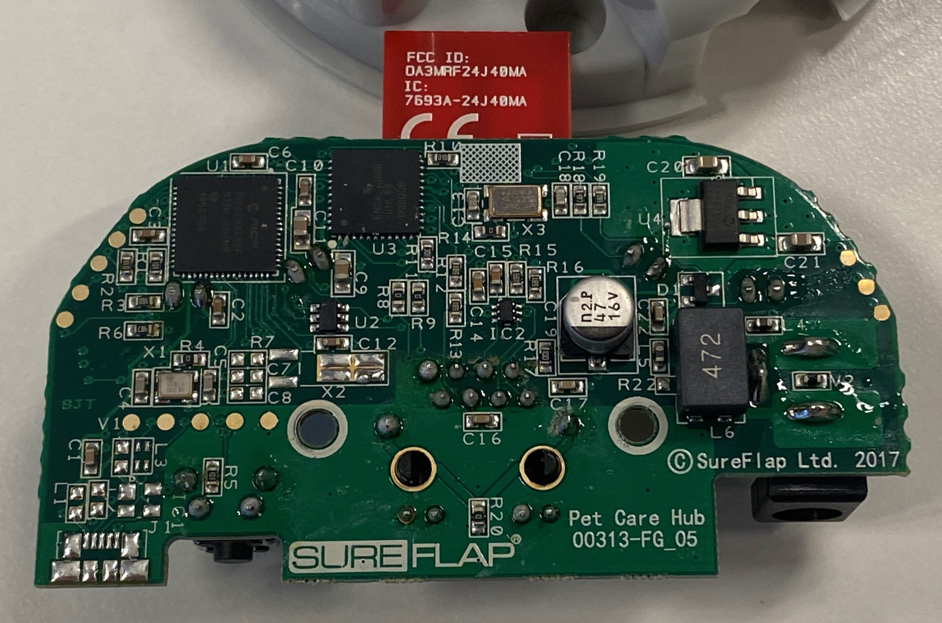
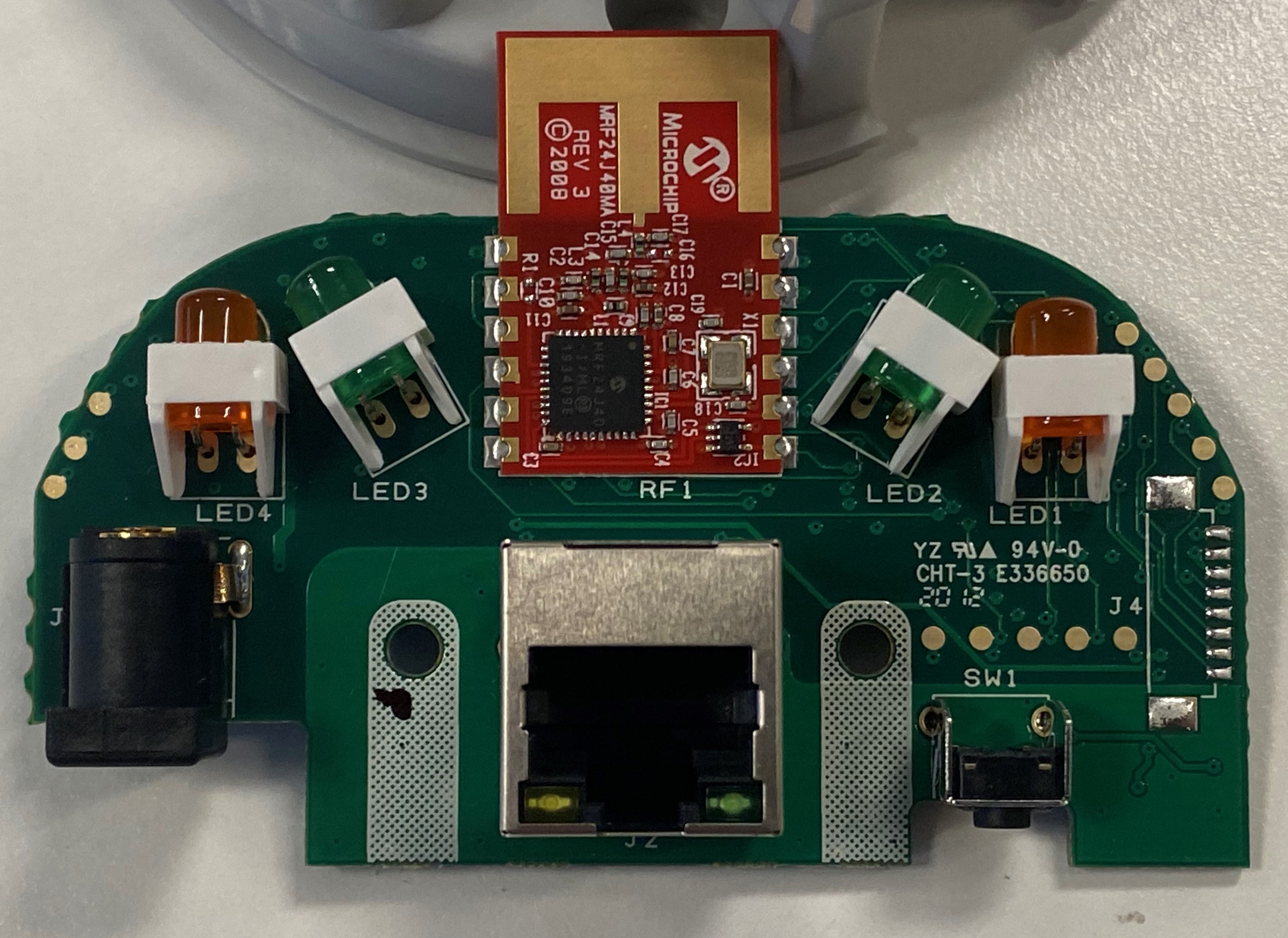
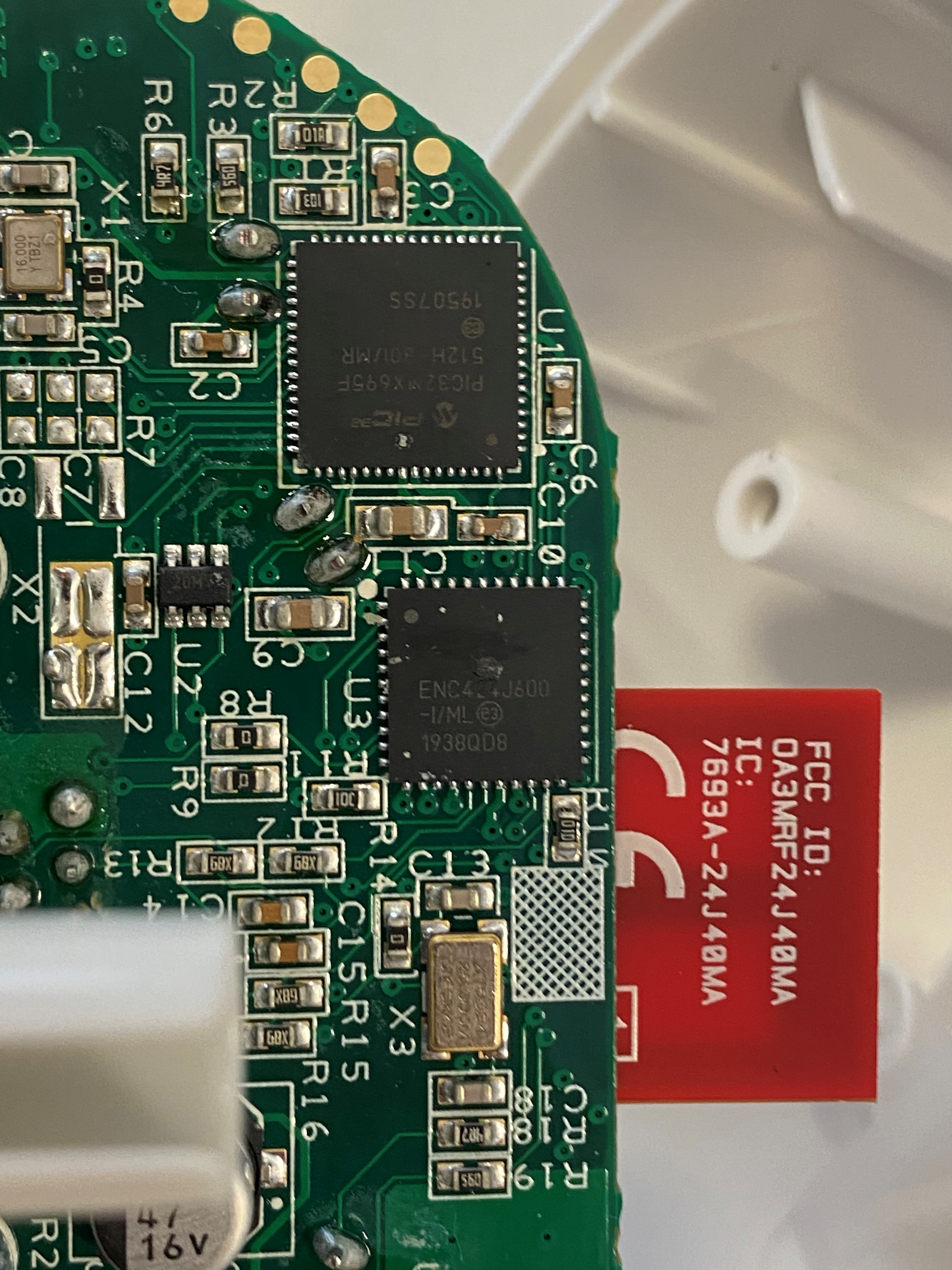
Hub Teardown
Hub pins
| Component | Description |
|---|---|
| CPU | PIC32MX695F512H - PIC CPU in 64 Pin (H version) TQFP form factor |
| Radio | MRF24J40 - Microchip Zigbee / MiWi radio controller |
| Ethernet | ENC424J600 Ethernet controller |
Datasheets
Below is links to the datasheets found on the Microchip site, these links may break so the PDFs are also downloaded and included here.
PIC32MX
There are two revisions of the PIC32MX and I find the v2 better.
Datasheets
- https://ww1.microchip.com/downloads/en/DeviceDoc/PIC32MX_Datasheet_v2_61143B.pdf - PIC32MX_Datasheet_v2_61143B.pdf
- https://ww1.microchip.com/downloads/en/devicedoc/pic32mx_datasheet_v1_61143a.pdf - Also V1 if required (for completeness)
- https://www.microchip.com/content/dam/mchp/documents/MCU32/ProductDocuments/DataSheets/PIC32MX5XX6XX7XX_Family)Datasheet_DS60001156K.pdf - There is also a specific PIC32MX6xx/7xx series datasheet which is much the same information as the above two datasheets:
- https://www.microchip.com/en-us/products/microcontrollers-and-microprocessors/32-bit-mcus/pic32-32-bit-mcus/pic32mx - Main page
MRF24J40MA
The radio is a MRF24J40 but it is in the MA package so you will need the main datasheet for the information about the CPU and the MA datasheet for the board pin information: MRF24J40: https://ww1.microchip.com/downloads/en/DeviceDoc/39776C.pdf MRF24J40MA: https://ww1.microchip.com/downloads/en/DeviceDoc/MRF24J40MA-Data-Sheet-70000329C.pdf Main page: https://www.microchip.com/mrf24j40
High resolution photos
High resolution photos of both sides of the hub:
Front
Back
CPU
Hub pins
The pads on both sides of the board connect to the other side, so the below photos show the pin connections on both sides of the boards. This may not be 100% correct so please check this before connecting anything.
The serial port speed is 57600 8/N/1 with flow control disabled.
Front with pins
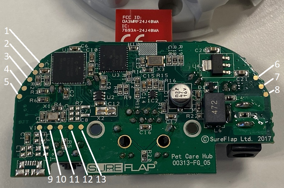
Back with pins
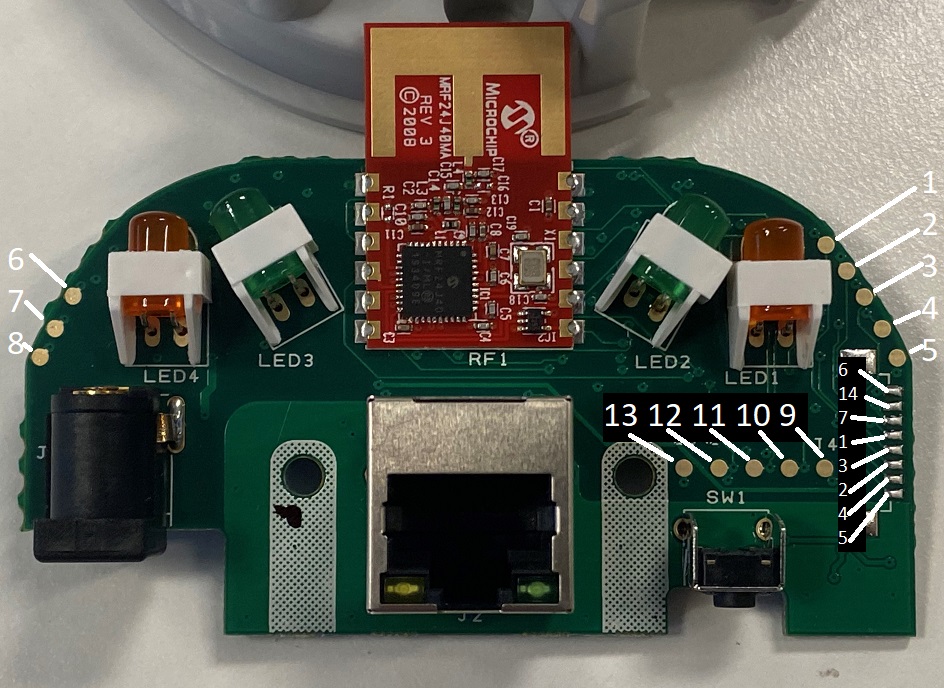
| Pin Number | CPU Pin | Description |
|---|---|---|
| 1 | 17 | PGC2 used for ICSP debugger |
| 2 | 7 | /MCLR via 100R |
| 3 | 18 | PGD2 used for ICSP debugger |
| 4 | 31 | U2RX - UART RX for the serial console |
| 5 | 32 | U2TX - UART TX for the serial console |
| 6 | 10, 26, 38 | Vdd - 3.3v power supply |
| 7 | 9,25,41 | Vss - Ground for UART and ICSP |
| 8 | - | Vin 5Vdc barrel plug |
| 9 | - | USB connector (unpopulated) USB+? |
| 10 | 36 | USB D- (unpopulated L3) |
| 11 | 37 | USB D+ (unpopulated L3) |
| 12 | 61 | PMD0/RE0 Connected to Reset Button |
| 13 | 9,25,41 | Vss - Ground for UART and ICSP |
| 14 | - | NC |
Side connector pin mapping:
| Pin | CPU Pin | Description |
|---|---|---|
| 6 | 10, 26, 38 | Vdd - 3.3v Positive supply |
| - | NC | |
| 7 | 9,25,41 | Vss - Ground |
| 1 | 17 | PGC2 used for ICSP debugger |
| 3 | 18 | PGD2 used for ICSP debugger |
| 2 | 7 | /MCLR via 100R |
| 4 | 31 | U2RX - UART RX for the Console output |
| 5 | 32 | U2TX - UART TX for the Console output |
Console Boot Message:
The hub doesn't output too much during boot until you enable debug messages: Standard boot message:
    SureFlap Hub 12:45:09 Jan 17 2020
    Build Number 43
    ---------------------------------
            Serial: 48 30 3x 30 2d 30 3x 3x 3x 3x 3x 3x 00
            As text: H0x0-0xxxxxx

    Stack Top: 0xa001ff88

    MAC address = xx:xx:xx:xx:xx:xx:xx:xx
    Read channel f from EEPROM
    Warning trying to change channel to f
    Set PANID to 3421
            [------------- Paired Devices ------------]
            [-----------------------------------------]
The above MAC address is the Zigbee Wireless MAC address not the ethernet MAC address
Debug Menu
The Debug menu can be enabled if you send an upper case "A"
    A - Enable debug console
    c/r - After debug messages are enabled hitting enter gives the below debug menu.

    SureFlap Hub Debug Menu
    -----------------------
    e - Dump list of application errors
    h - dump entire hub register entry table
    p - dump pairing table
    l - Toggle Ethernet RJ45 LEDs
    s - Dump set_reg_queue
    t - Spam RF requests to test buffering
    z - disconnect and zero connection table

    Please select
    Other commands:
    miwi_channel_noise_floor addr=23

    RF Channel Register = 24
    1 - Set Channel to 15 (0f)
    2 - Set Channel to 20 (14)
    3 - Set Channel to 26 (1a)
    r - Doesn't give an error, I think it does a ping over MQTT.
    v - Unknown
his the same output as sending aTS 1000 3 0 205message over MQTT.zis the same as pressing the button underneath to start paring.pPairing table you get, this corresponds to the 8 status register bytes:
    [00]: valid=0 online=0 type=0 last_heard=0 >>00:00:00:00:00:00:00:00<<   -]
    [01]: valid=0 online=0 type=0 last_heard=0 >>00:00:00:00:00:00:00:00<<   -]
    [02]: valid=0 online=0 type=0 last_heard=0 >>00:00:00:00:00:00:00:00<<   -]
    [03]: valid=0 online=0 type=0 last_heard=0 >>00:00:00:00:00:00:00:00<<   -]
    [04]: valid=0 online=0 type=0 last_heard=0 >>00:00:00:00:00:00:00:00<<   -]
    [05]: valid=0 online=0 type=0 last_heard=0 >>00:00:00:00:00:00:00:00<<   -]
    [06]: valid=0 online=0 type=0 last_heard=0 >>00:00:00:00:00:00:00:00<<   -]
    [07]: valid=0 online=0 type=0 last_heard=0 >>00:00:00:00:00:00:00:00<<   -]
    [08]: valid=0 online=0 type=0 last_heard=0 >>00:00:00:00:00:00:00:00<<   -]
    [09]: valid=0 online=0 type=0 last_heard=0 >>00:00:00:00:00:00:00:00<<   -]
If you enable debug when the hub first boots you get a lot more information:
    | Talking to: hub.api.surehub.io | Socket Obtained | Socket Opened | Socket Secured |
    --- Processing Response: 17 Bytes Total
    1 bytes remain, after 2 reads.Found status = 200
    0 bytes remain, after 3 reads.  | Tstate 2 |
    --- Processing Done

    --- Processing Response: 275 Bytes Total
    0 bytes remain, after 35 reads..Content Length = 3573           Start receiving non-chunked data, length=3573
            | Tstate 4 |
    --- Processing Done

    --- Processing Response: 3573 Bytes Total
    0 bytes remain, after 447 reads....     | Tstate 5 |    TCP_RESPONSE_COMPLETE
    --- Processing Done

    -------- Credentials Decoded --------
            Host:           **8th Field in Creds file**
            Client ID:      **3rd Field in Creds file**
            Base Topic:     **7th Field in Creds file**
            Version:        **1st Field in Creds file**
            ID:             xxxxxx (Serial Number which is also 2nd field ) and ClientID as a single string
            Username:       **4th Field in Creds file, should be empty**
            Password:       **5th Field in Creds file, also empty**
            Network Type:   1 **6th Field in Creds file**
            Certificate:    **9th Field in Creds file**

            Length:         xxx
            Cert Hash:      0x xxxxxxxx
            Key Hash:       0x xxxxxxxx

    -------- End Credentials --------

    Connected
    LED new mode a 5 Closing Socket
    Web state=3 Calling connect... Connection made!
    Connection sequence done.
    RF reset
    Web state=5 Subscribing to Hub Messages: Success!
    LED new mode 5 5 Web state=9 TCP Bytes Put: 2852, Seconds: 60
    Set LED to 0
    LED new mode 0 5 Unknown command 71